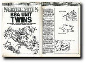
Introduced in 1961 for the 1962 season, the A50 and A65 unit twins, with their egg-shaped engines of 500 and 650cc were called, unkindly by some, Unit Destruction! But this was almost always the way when anything new came onto the market, especially so in this case when they were to replace the much loved A10.
The early Star Twin models, with their low 7.5 to 1 compression ratio, proved to be very reliable, in fact the one I once owned covered some 65,000 miles, without an engine strip! Despite the critics, the whole engine complex was much easier to clean and work on than its predecessor, especially the pushrod setup!
Before commencing it is advisable to have a good set of spanners and a socket set — for the earlier models this will mean BSF/WHIT, and the larger ones AF/ UNF. We’ll forget the mid range ones which had a combination of both! You will also need an overhaul gasket set and the usual things like feeler gauges, grinding paste, scraper tool, valve spring compressor, access to a clutch puller, valve grinding tool, and possibly a two leg puller is also necessary.
 New items I recommend changing on each major overhaul include: piston ring circlips, valve springs, big end nuts and bolts, gaskets, piston rings, and oil. Replacement of other items like pistons, big end shells, bearings and bushes will depend on the amount of wear incurred.
Remove the engine unit from the frame. This will entail removal of the petrol tank, exhaust system and carburettors; disconnect the electrical wires, drain the oil from both the sump unit and the tank, remove head steady and oil pipes. The rear chain and chainguard will have to be removed, as will the clutch cable and rev counter cable, if fitted. Remove the plugs and HT leads.
The engine unit is now held in by its mounting bolts only and once undone, there is a knack to getting it out of the frame. Lift the back slightly, twist and Iift out on the left hand side, complete with the rear engine plates. I always find it easier to manoeuvre it with the cylinder head removed, before lifting it out.
There are slight variations between the 1962 and 1972 models but basically the units are the same. First, remove the rocker box cover — six nuts on earlier models, four bolts and two nuts on the later ones. Before the cylinder head can be removed, the exhaust rocker has to be removed to gain access to the two front cylinder head bolts; the inlet rocker assembly can be left alone. It may be necessary to remove all pushrods before the centre head bolt can be removed. This is where a socket or box spanner is essential?
 If a fairly high mileage has been covered, then replace the valve springs as a matter of course. If in doubt, valve spring free lengths are: inner 1 7/16″, outer 1 3/4″. Removal with a special valve spring compressor is the only way to ensure you don’t lose the collets from the tapered spring caps. Now that the springs are removed, the valve and guides can be checked. If there is excessive side-play then the guide will probably need renewing, and possibly even the valve.
Guides can be driven out with a special punch-like tool that fits snugly into and onto the valve guide. Pre-heat the cylinder head first and replace the guides while the head is still warm.
If new valve guides are fitted, or new valves used, the valve seat in the cylinder head must be recut. Valves need replacing if there are signs of bad scoring on the stems or deep pitting or burning on the valve face. Providing the pitting is not too deep, the valves can be refaced on a specialist machine. All valves whether new or old should be ‘ground in’ before assembly.
Remove all carbon from the cylinder head and ports — final cleaning can be done with wet and dry paper and, if you are really keen, metal polish. Smear a little oil on the valve stem, and a little valve grinding paste on the valve seat; replace the valve in its correct seat and using a valve sticker tool, rotate the valve back and forth, lifting every two or three turns and replace it in a new position.
Keep grinding until a smooth matt finish all around the seat is achieved, without any black marks. Before reassembly, ensure all traces of grinding paste are removed. Oil the valve stems, replace the springs and refit the collets using the compressor tool.
 Whilst the pistons are still in the bores examine for side movement. If excessive, take the pistons down the bore slightly and examine to see if there is a ridge at the top — if there is then a rebore is necessary, with new oversize pistons. If in doubt have the bores measured with a dial gauge. The STD (standard) bore pushrods should also be checked for damage, like chipped or loose cup ends, and to ensure they are not bent. If in doubt, replace them.
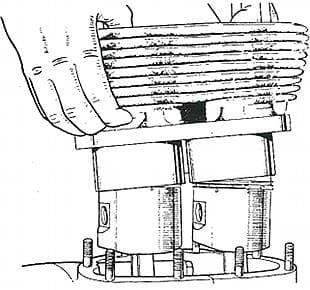
To remove the barrel see that the pistons are at the bottom of their stroke, and carefully lift them off, after, of course, removing the holding down nuts. The tappets should be held in the barrel with small circlips; now is the time to examine the tappets for wear and check the camshaft too, at the rear of the crankcase mouth.
Removing the pistons
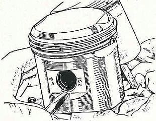
Before removing the pistons from the conrods, take note and mark them if necessary, so that you can replace them the right way round and in the correct bore (providing you are not replacing then). Prise the circlip out of the piston groove with a sharp ended tool (an electrical screwdriver will do). If the gudgeon pin is tight, the piston may need warming a little, using a rag which has been in hot water and then wrung out.
If you are not renewing the pistons, it is advisable to fit new rings. The correct fitted gap for the rings should be .008in to .013in — check one in your bore, off the piston! Use an old ring to clean out the grooves in the piston and deglaze (take the shine off) the bore before fitting the new rings.
Removal of the clutch cover is simple enough, as is the removal of the clutch plates. However, you will probably need an extractor tool to remove the clutch hub.
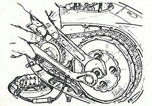
Remove the mainshaft nut either using special tool no.61-3768, which is in effect just two clutch plates bolted together (at least that’s how we made one!) or fix a chain around the gearbox sprocket and bolt in place. A bar through the conrod eyes will assist in removing the crankshaft rotor nut. Remove the stator, rotor and clutch and engine sprocket together and check them for wear. However, the clutch assembly is an article on its own!
On to the timing or gearside. Remove both kickstart and gearlever and release the cover which is held on with three screws. Remove the points plate and the advance and retard unit, the latter either with special tool no. 61-3005 or screw a bolt into the nut and strike it sharply with a mallet. This should loosen it from its taper.
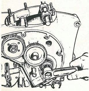 Remove the oil pump and crankshaft nut and then the timing gears; there is no need to remove the camshaft pinion unless the camshaft is being renewed. A two-legged puller may be necessary to remove the crankshaft pinion. The gearbox need not be disturbed unless you are stripping it, and the unit can stay in place.
Before removing all the bolts and nuts holding the crankcase halves together, a test to discover the condition of your timing-side bush can be done. Hold the end of the crankshaft and test for movement up and down, if excessive you will know before further measuring that it will need replacing.
A preliminary check on the big ends can also be done. Once again, check for up and down movement; in this case it should be zero. Maximum wear on all journals is .002in.
Once the crankcases are parted and the crankshaft removed, a proper check can be made. Whether the crankshaft is reground or not, the sludge trap plug should be removed and the oilway cleaned thoroughly. The conrods themselves are easily removed, and if in doubt about wear, do get the journals measured.
Timing-side bush
Here at Bri-Tie, we replace the usual timing-side bush, with one made of phosphor bronze, to suit the crankshaft which is machined to the minimum. Of course, this enables the crank to be machined many more times, rather than jumping from .010in to .020in to .030in.
We do supply ‘stock’ bushes as well but the bronze bush, made of good material, is, we feel, a far better job and the next best thing to the roller bearing conversions offered by Devimead, “the A65 people”, and SRM of Cardiff. These conversions are obviously far superior, especially if you intend using the bike for long, high mileages.
Crank balancing is another extra that can be undertaken to eliminate some of those twin vibrations.
Reassemble with extreme cleanliness, especially the big end conrod assemblies. Torque the conrod nuts to 221b/ft, new bolts and nuts being recommended. If any other bushes in the crankcases need replacing, then remember they will probably need reaming out and the camshaft bushes reamed in line with the crankcases bolted together.
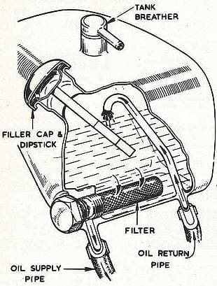 Replace the crank into the timing side casing, being careful to avoid damage to the bush. Bolt up the other case half and check for side movement (end float), this should be adjusted to .002in to .003 in, by the use of shims. Once this end float is achieved, the crankcases can be bolted up using jointing compound between the halves. Make sure both crankshaft and camshaft turn freely, before refitting all the other parts.
Replacing the barrels onto the pistons is helped greatly if piston ring clamps are used and steady blocks are used across the crankcase mouth.
When replacing the cylinder head, torque all bolts down to 28/301b/ft and nuts to 31/321b/ft. Start with the centre bolt and work outwards. Replace the two short pushrods to the outer tappets and under the inlet rocker arms; replace the long rods to exhaust rocker arms. Adjust the tappet gaps .008 in inlet .010in exhaust and replace the cover using a new joint. Replace all other units in the reverse order of dismantling.
Some points to remember: refit the engine into the frame from the left hand side; the oil pipes are crossed over. We recommend using a straight SAE 40 or 50 oil in the engine and a regular oil change at 2,000 to 2,500 miles. Use EP 90 in the gearbox.


