Chapter 4. Wherein a letter arrives, a crankcase departs, a gearbox re-build goes awry… demonstrating why Jim Algar doesn’t rebuild classic Nortons for a living…
To begin, this is actually Chapter 4, Version 2.0. Version 1.0 was almost complete and sitting safely on my computer’s hard drive when I decided (foolish man!) that said hard drive needed a little house-cleaning and re-organizing… whereupon I managed to re-organize Chapter 4 right out of existence. (Insert sharp, monosyllabic Anglo-Saxon word here). So, let’s try again, shall we?
Enjoy more classic motorcycle reading, Click here to subscribe to one of our leading magazines.
Joy! The post has brought a letter all the way to California from England, from Les Emery at Norvil. I had sent him a longish letter, complete with photographs of my damaged crankcase (see Chapters 1 and 3), which ended with three basic questions:
Les is, evidently, a man of few words: three, in this case, which he simply penned next to my questions, then re-sealed the letter and returned it. His replies?
In a subsequent phone conversation with Les, he explained that he sees the timing side damage all too frequently. It happens, he says, when someone tries to remove the crankshaft pinion gear without benefit of the recommended Norton tool. Rather, he says, they jam a screwdriver or pry bar behind the pinion and heave away, with the result that the ill-chosen tool does not budge the pinion but instead inevitably breaks through the thin aluminum of the crankcase. I’m glad I used the proper tool to pull my pinion; I would not want to personally face the disapproval and scorn apparent in Les’s voice.
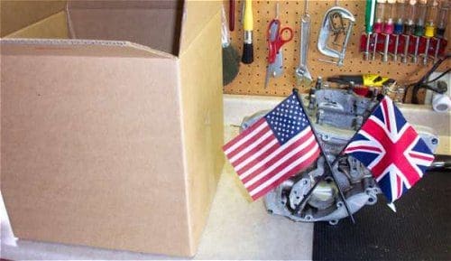
All right; a suitably sized box, some bubble wrap, and I can have my crankcase off to Jolly Olde Englande for repair. No, wait; I’ve a task to take care of, which I’ve been holding in abeyance awaiting word from Les. You see, the crankshaft bearings are still in the case halves; the complete bearing in the timing side and the outer race in the drive side. All the manuals I’ve read describe their removal as follows: heat up the crankcases until they’re ‘bubbling-spit’ hot, which expands the bearing areas and will allow the bearings to be removed.
Tell the truth, I’ve always wondered about that. I mean, it seems so low tech. And can that actually be how the bearings were installed in the first place? I try to picture shop-apron wearing denizens of Bracebridge Street all hovering over a bank of ovens like housewives waiting for a souffle to rise. Quite a picture, innit?
And then there’s the problem of convincing one’s life partner that she should allow you to chuck greasy, sharp and angular pieces of aluminum into the very oven that cooks the family meals. (A little truth in advertising here, actually; neither of us is much of a cook, and will have dinner out at the least excuse). But bless her, she at least grasps the physical principals involved. ‘Makes sense,’ she says, ‘go ahead.’
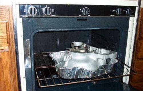
Okay, timing side first, as it’s the easier of the two. Since the entire bearing is still in place, the inner race can be used as a surface to apply some force. So into a 500-degree oven it goes; after ten minutes or so out it comes, and a large socket is placed on the inner race of the bearing. A healthy push and it obligingly drops out of the case. (All this is done with a sturdy pair of oven mitts, of course; 500 degrees is bl**dy hot!)
The drive side is a bit harder; with only the outer race of the bearing in place, there’s nothing to push or drive on. So here’s the drill; ten minutes in the oven, take it out, rush out of the house to the front (concrete) step, and bang the case down on the concrete repeatedly while praying that gravity and momentum will smile on you. Bang! Bang! Then Bang!/Ring!, an altogether lovely sound as the bearing race happily falls onto the concrete. Well, I’ll be dipped! It works!
So that’s the crankcase. As I write this, it’s winging its way over the Atlantic to Les, courtesy of the US Postal Service. Actually, I seriously doubt that ‘winging’ is the right word. Four to six weeks, they said. Oh, it could have been faster, but at the rates they were quoting to me, they can …um….well, never mind.
On to the gearbox then, which I’ve already disassembled (see Chapter 3). An examination of its component parts is encouraging. The hard parts, gears and shafts, all look to be in good shape (for the time being; more on that in a minute). It’s the spinney / rotatey parts, the bearings and bushes, that are showing some wear, as you’d expect, given that they’ve been spinning and rotating furiously in the dark for decades.
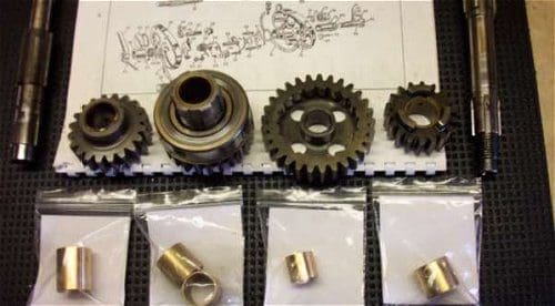
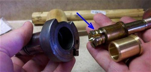
So bushes and bearing are ordered and duly arrive. Most of the bushes are an easy fit into the gears and onto the shafts, though a couple need a little judicious reaming (insert tasteless joke here) to be persuaded. The real tough character is the layshaft bushing in the kickstart shaft. It’s in a blind hole, so it can’t be driven out. I’m unsuccessful in my search for an inside pulling tool with legs long enough to get in past the bushing, and I’m stymied until an inspired bit of lateral thinking (courtesy of a mate at work) sends me to my local DIY store to buy…. wait for it… an expanding masonry anchor!
If you’ve never seen one of these, picture a long, hollow stud, threaded on one end for a large nut, with the other end serrated and cross cut up its length for an inch or so. Inside the stud is a central spike which, when driven into the stud from the threaded end, expands the serrated end by opening it up like the petals of a flower, thus firmly wedging and anchoring the stud in the concrete. In my case, I pickup up an anchor of a diameter that just allowed the serrated end to be pushed into and past the bush. Then a few hammer blows on the spike expanded the serrated end where it sat behind the bush, and the whole thing, with the help of a nut and some spacers, could be pulled out of the kickstart shaft, bush and all. Voila! (The photo says it better that I can.)
At this point things were looking good, but it was at this point that I managed to screw up royally (a fine American phrase, despite its monarchical connotation). I briefly considered leaving this incident out of my sporadic narrative, for reasons of simple embarrassment, but I’m much too old to worry about such things now. So…
I was at the point of putting the new bush into the kickstart. It should, I thought, easily drift into place. This is when I made a Monumentally Bad Decision. I decided that the easiest way to drift the bush in would be to use the layshaft itself as the drift tool. After all, I thought, it shouldn’t take but light tapping to drift the bush into place. Well, the tapping got a little beyond light, and with one slip of the hammer, I became the not-so-proud-and-in-fact-thoroughly-chagrined owner of a ruined and useless layshaft…
@#$%! Children, don’t try this at home. And yes, of course I Do Know Better. Well, another item for the Learn From Bitter Experience drawer in my mental filing cabinet… said drawer occupying a stunningly large expanse of my grey matter these days.
So… a call to Norvil. Yes, the layshaft is available. Yes, it’s expensive. Oh, actually it’s on back order. No, we don’t know when. Yes, of course you’ll be informed soonest. @#$%!
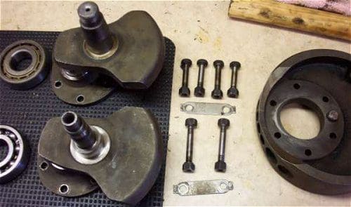
All right, so the gearbox goes back on the shelf. What to do next, that I might manage without self-initiated disaster? Well, the crankshaft sludge trap could use a good cleaning out. The Norton design is three-piece bolt-up affair, with a central cast iron flywheel sandwiched between the cheeks of two forged half cranks. This came apart easily, the sludge cleaned out quickly, and the whole thing quickly bolted back together with thread lock compound and tab washers as appropriate.
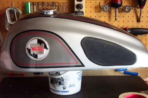
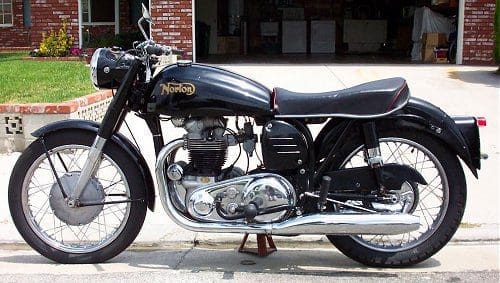
Hmmm, what else can I address? Ah yes, the gas tank. (Yes, I know it holds petrol, but can we not be internationalists?). As mentioned before, the bike came with two tanks; one on the bike which, though serviceable, has been treated to considerable filler and carries nonstandard badging… and a beautifully restored and re-painted tank just waiting for the correct badges and knee grips. The round badges were located on eBay, and some lovely and correct knee pads came my way through the ever-generous efforts of Steve the Toast, who managed to track them down for me. Muchas gracias, Esteban!
Since the knee pads are stick-on types, the question of the proper adhesive was bandied about. I decided to try a 3M automotive product, General Trim Adhesive. Available in a spray can, it is advertised as being suitable for attaching all kinds of trim – carpet, headliners, upholstery, vinyl and rubber – to painted surfaces. So…spray, stick, a little masking tape (well, a lot, really) to hold it flat to the tank, come back in 24 hours.
Result?
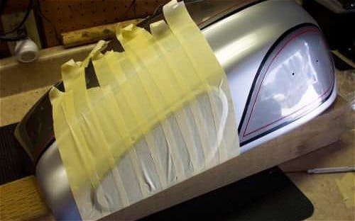
Failure. It was all right on the flat part, but the top of the knee pad has to follow the curve of the tank… which is where the adhesive failed to hold. Hmmmm. It turns out that the adhesive was very happy to grip the tank; is was the rubber of the knee pad that it wouldn’t adhere to. I had given the pads a good washing first, to remove any mold release agents or other suspect substances, but some areas of the pads came away suspiciously free of any adhesive residue when I peeled them off the tank. So, back to the drawing board.
Which is when I remembered that I had used another 3M product, Super 77 spray adhesive, to fix a rubber work mat to the top of my workbench, on a Formica surface. Tenacious doesn’t come close to describing the bond it provided. So, yes… spray, stick, lots of masking tape, 24 hours later… success!
And I’ve just heard from Norvil this morning… the layshaft is on the way. Things are looking up. Except for one thing: I’m now at Chapter Four of this epic, and what do I have to show for it? An engine in pieces, a gearbox in pieces, everything else in pieces, and a nice, shiny petrol tank with no motorcycle to slide under it. Frank W, on the other hand, managed to completely rebuild his Ariel from a smoking heap to a glorious-looking bike in just twelve installments. Hmmm. Although it’s just possible he’s done this a time or two. And one should have role models, shouldn’t one?
Gearbox re-assembly next, and waiting to hear from Norvil about my crankcase. Stay tuned.
